Reflected Risk: Alarm Zoning Where Solar Retrofits Meet Temporary Scaffold
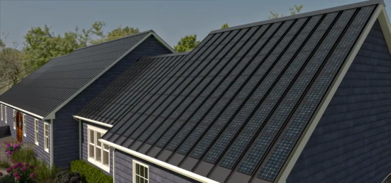
Photo: Wikideas1, CC0, via Wikimedia Commons
A solar PV retrofit is rarely just a roofing job. It introduces a dense concentration of high-value equipment — modules, inverters, isolators, mounting rails and long cable runs — onto a building that may previously have offered little of interest to a thief. At the same time, the temporary scaffold erected for the works creates a structured route from ground level to the roof edge. The alarm design has to treat that combination as a single security problem, not as a scaffold alarm with a few sensors added near the panels.
Why a PV retrofit changes the alarm brief
The threat model on a domestic or commercial PV project is broader than the usual scaffold perimeter. Modules have resale value, inverters are portable and expensive, and DC cabling contains copper and aluminium that can be stripped. The roof access point — whether a hatch, a dormer, a stair core or simply the scaffold lift that meets the eaves — becomes the hinge between the temporary works and the permanent asset.
A conventional scaffold alarm configured around the external face may perform well against approach from the street but poorly against movement that begins on the scaffold and ends at the array. The brief should therefore identify the assets to be protected, the routes to them, and the legitimate movements that will occur during installation. That information belongs in the zoning plan before any bracket is fixed.
Zoning by asset and approach, not by elevation
A common weakness is to create one large detection zone across the scaffold face nearest the PV array. This produces a simple drawing but a poor security outcome: a single activation gives the response team little indication of whether the event is at the array, at the inverter position or at the cable route.
A more defensible approach is to divide the scaffold into zones that follow asset groups and approaches. The array itself may justify a detection field along the roof edge or across the access route to the modules. The inverter position, often at high level or within a roof space, may need its own zone if it is reachable from a scaffold lift. Cable runs — particularly where they drop vertically or pass through a temporary opening — should be considered as a separate line of risk.
The zoning plan should also show the legitimate installer corridor. If the only route to the array passes through a zone, the alarm will be isolated repeatedly during works unless that movement is designed into the scheme. Planned isolations with logged reinstatement are preferable to ad hoc silencing; the evidence value of a controlled isolation is considerably higher than a gap that nobody recorded.
Designing out glint, heat and legitimate movement
Solar modules are reflective, and low sun angles in the UK can produce rapid changes in the infrared field seen by passive detectors. A sensor aimed across the face of an array may be reliable at midday and troublesome at dawn or dusk. Detection fields should generally be arranged across the approach to the array rather than across the reflective surface itself, and mounting positions should be tested at the times of day when glint is most likely.
Heat is the second environmental factor. Inverters and other plant generate thermal plumes, and a detector mounted directly above or beside them may experience exactly the kind of rapid temperature change that produces nuisance activations. Physical separation, sensitivity adjustment and, where appropriate, dual-technology detection can reduce the problem, but the first control is position: keep detection fields away from plant that will heat and cool during the day.
Legitimate movement during the retrofit is the third factor. Installers will carry modules, tools and cable across the scaffold, often outside core working hours. The alarm design should distinguish between the working day and the protected period, and the handover file should record how the transition is managed. Engineer modes, timed isolations and clear reinstatement checks are all part of the zoning scheme, not an afterthought.
Handover evidence for PV projects
On a PV retrofit, the alarm is protecting an asset that will remain after the scaffold has gone. That makes the handover file more important than on a short-term works package. The file should include an as-built zone drawing, a schedule of protected assets, a record of isolations and reinstatements, and the commissioning results for each detector.
Where the alarm is intended to support an insurance position, the evidence should show that reasonable steps were taken. A zone map that identifies the array, the inverter and the cable routes is more persuasive than a generic certificate. An event log that records activations, isolations and restorations gives the insurer a readable narrative. The same discipline supports the principal designer and temporary works coordinator, who need to see that the security arrangement has been coordinated with the scaffold and the PV installation rather than added retrospectively.
Commissioning checks before the scaffold comes down
The final commissioning window is the last opportunity to test the alarm against the conditions that will actually exist on site. A walk test should be carried out at more than one time of day, with particular attention to low-sun glint. Detectors near inverters should be observed through a heating cycle. The installer corridor should be walked to confirm that legitimate movement does not produce repeated activations, and the isolation and reinstatement process should be rehearsed.
Battery autonomy, tamper detection and warning boards should be checked in the same visit. Once the scaffold is struck, the detection fields will change; a post-removal review should confirm that the zones still cover the array, plant and cable routes without creating new nuisance sources.
Solar retrofits reward a zoning approach that treats the scaffold as a temporary access route and the PV array as a permanent asset. The objective is not more sensors, but a clear separation of risks — array, plant and cable run — with detection fields positioned to avoid the reflections and heat that make exposed sites difficult. That is the difference between an alarm that protects the installation and one that merely protects the scaffold.